Technical overview.
Overview.
The mechanical team for the 2024-2025 academic year focused on optimizing the present systems on Qubo developed last year. The main systems optimized are the dropper, claw, and vertical camera systems. New pistons and improved placement for the dropper, claw, and vertical camera will improve Qubo’s capability with the appropriate competition tasks. The torpedo team made key advancements to give us a pioneering edge in competition with the powered torpedo last year and has continued to improve and refine the design and operation of the system. Key developments made for the autonomous torpedo platform will have an unprecedented impact on the competition landscape once complete.
Mechanical.
Pneumatics System.
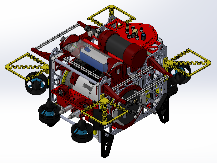
The pneumatics system is responsible for actuating the torpedo launcher, marker dropper, and claw end effectors. Compressed air is regulated from a paintball tank into an enclosure containing four 12V solenoid valves. These valves direct air to four double action pneumatic pistons that each control an end effector. This system creates a much more reliable method of actuation compared to servos, which have proven to be unreliable underwater. Rotational motion is also much less valuable than linear motion. Using pneumatics avoids having to design complicated mechanisms to produce motion easily achieved with pistons.
During last year’s competition, a leak in the flow regulator allowed water to enter the solenoid valves and drain to the bottom of the pneumatics hull, damaging the circuit board inside. To prevent this from happening again, the board was moved from the bottom to the top of the pneumatics hull and mounted upside down. This way, any leaking water will drain to the bottom away from the board.
Chassis.
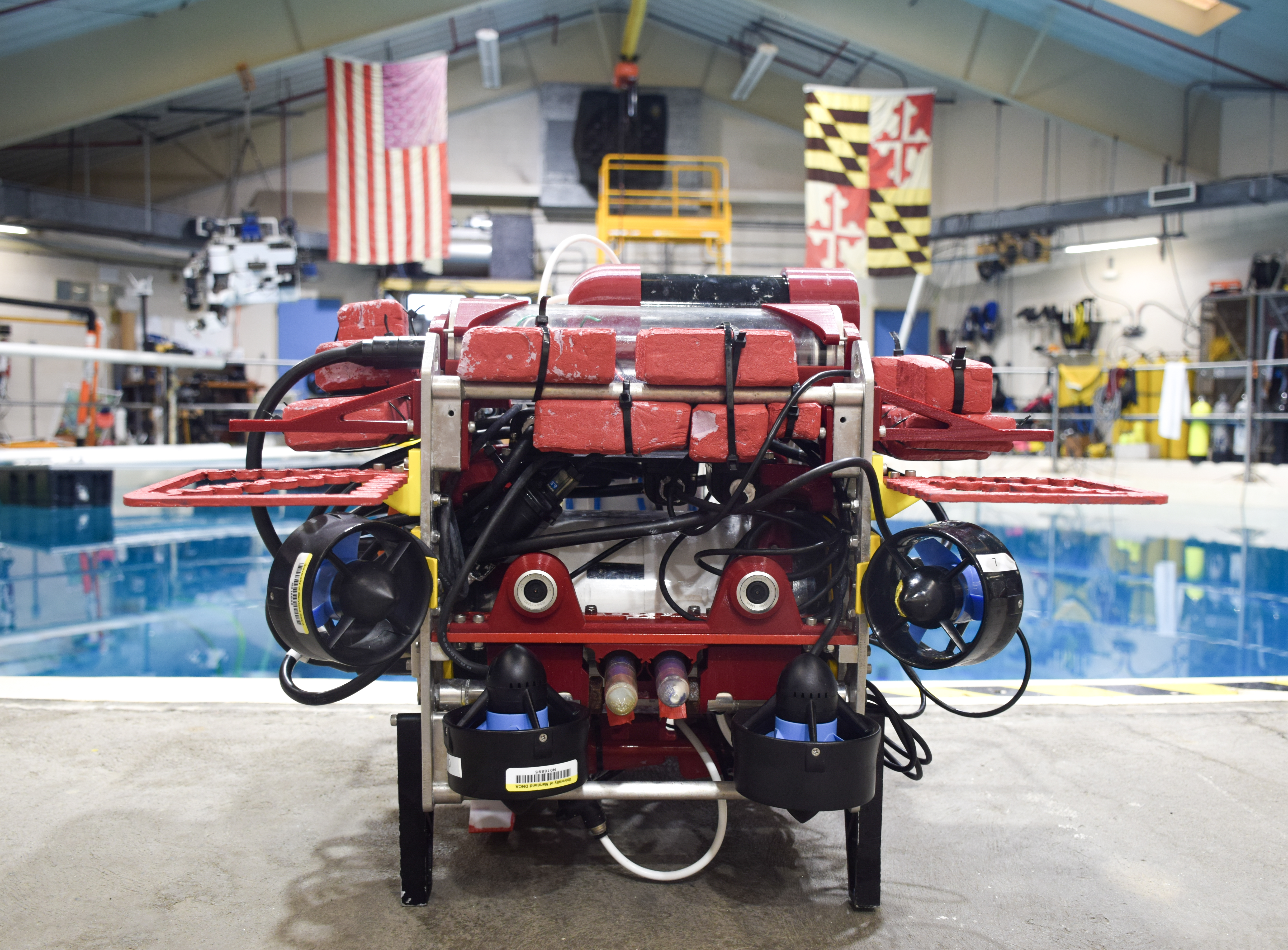
The framing we inherited remained unchanged from last year’s frame, two main side plates with smaller framing plates and rods connecting the main side plates, aside from cosmetic changes. The bare metal theme of the framing was basic and unattractive so we powder coated all major parts except for the two side plates for a Maryland color theme. While not necessary, presentation is a factor that we had potential to improve on in this year’s competition. These cosmetic changes help to bring Qubo together to show that we are one team, Robotics at Maryland.
Claw.
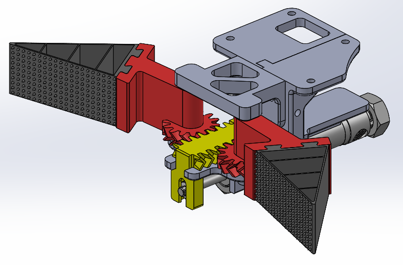
During the competition, Qubo will need to pick up irregularly shaped objects and place them in bins to score points. To do this, we developed a claw that uses a rack and pinion mechanism actuated by a pneumatic piston to open and close. To open the claw, the piston extends and pushes the rack forward. The rack turns the gears and rotates the arms open. The reverse happens to close the claw. The grippers are made of 3D printed TPU and are designed to conform to the shape of whatever they are grabbing. The triangular structure allows them to easily compress and curl around an object.
This year, the gear system was changed from spur teeth to helical teeth. This decision was made to reduce backlash in the gear meshing. The grippers were modified as well. The old gripping surface was made of a smooth wall of TPU, which offered little friction, making it difficult to grab objects. To increase the friction, spikes were added to the grippers, and they were sprayed with flex seal.
Dropper.
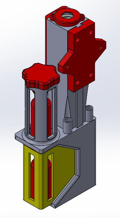
One task Qubo needs to complete during the competition is dropping a marker into a collection bin below. To do this, we designed a dropper mechanism that uses a pneumatic piston to actuate. The dropper is capable of housing two markers simultaneously, allowing for two distinct drops for redundancy. To operate, the piston extends and pushes a triangular wedge downwards. The wedge interfaces with an angled slot on the active cylinder. As the wedge moves down, it pushes the active cylinder forward outside the main body. The first marker falls due to gravity. When the piston retracts, the second marker falls into the active cylinder. The piston can then actuate again and drop the second marker. For this year’s competition, the piston orientation was changed from horizontal to vertical to save space on Qubo.
Autonomous Torpedo.
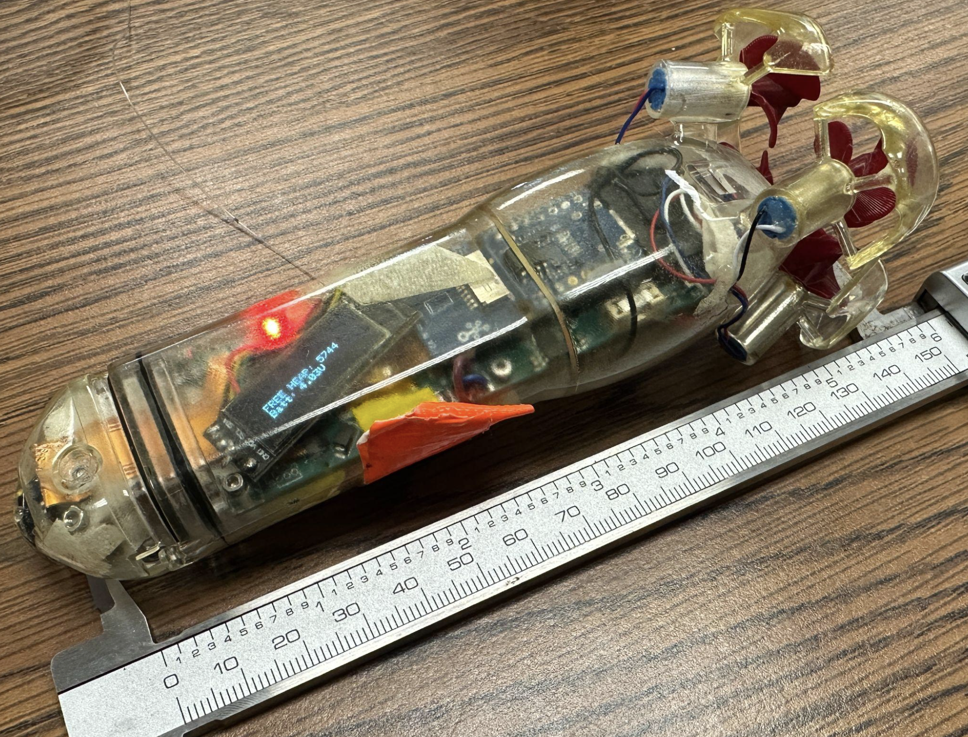
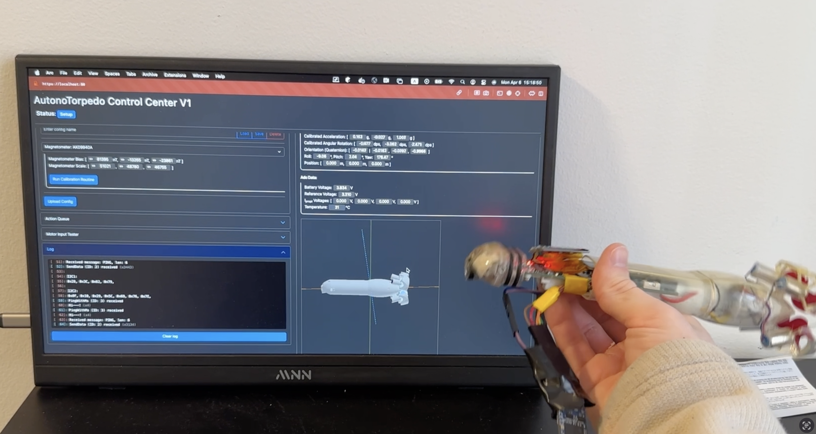
This extremely ambitious project had been in the works since the RoboSub 2024 competition as a follow-up to the powered torpedo. The project statement is simple: a fully autonomous vehicle that fits entirely within the 2x2x6 inch bounding box required for a torpedo (and a marker, since they share guidelines).
The design of the autonomous torpedo is split into the body, the head, and the inner skeleton. The body houses the four 7x16mm DC coreless motors, encases the inner electronics, and connects to the head via a double o-ring piston seal and two M2 bolts which keep the parts together. The head is bolted to the skeleton and the PCB, allowing all electronics to be accessed once the torpedo is opened. In the head are two adjustable weights which can be filled with metal for balancing, as well as multiple sensors such as the OV5647 camera, I²C pressure sensor, and I²C time-of-flight IR distance ranger. The skeleton holds onto the PCB and one-cell 550mAh LiHV battery in order to provide additional structure on the inside of the torpedo.
On the main PCB, an STM32G431 is used as a DC motor controller via PWM, a basic battery manager, and a sensor controller over I²C. The most important I²C sensors on the PCB are the 6DOF inertial measurement unit (accelerometer + gyrometer) and the 3DOF magnetometer, which are both used to aid in navigation. The I²C line also extends to the sensor flex PCB and connects to those two sensors. Acting as the brains of the torpedo is the Xiao ESP32, which connects to the STM32 through a separate I²C line in addition to the Grove AI vision model V2 and a 128x32 OLED display for better debugging when the torpedo is in use.
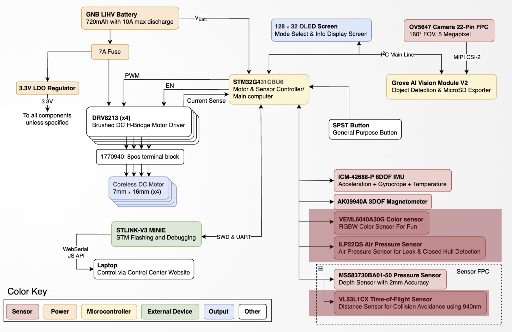
Lastly, the software side of things is slightly less developed, but the STM32’s job is separated into three sections. First it will take a desired heading and orientation from the ESP32 and maintain it according to the magnetometer’s reading of north. With four motors in a clockwise/counter-clockwise configuration, the control scheme of the torpedo nearly mirrors that of a mini quad-copter drone with 4 degrees of freedom: roll, pitch, yaw, and forwards. Current consumption of each motor is independently read and used to constantly adjust the PWM signal sent to each of the four DC motor drivers in order to achieve the torpedo’s desired heading/orientation. The second job of the STM32 is to read from all sensors and control them as needed. Lastly, it will monitor battery voltage and shut down the torpedo once it has dropped too low. All data read from the motor drivers, sensors, and ADC inputs is polled by the ESP32 at a constant rate, which computes its next action and then sends a chunk of data back to the STM32.
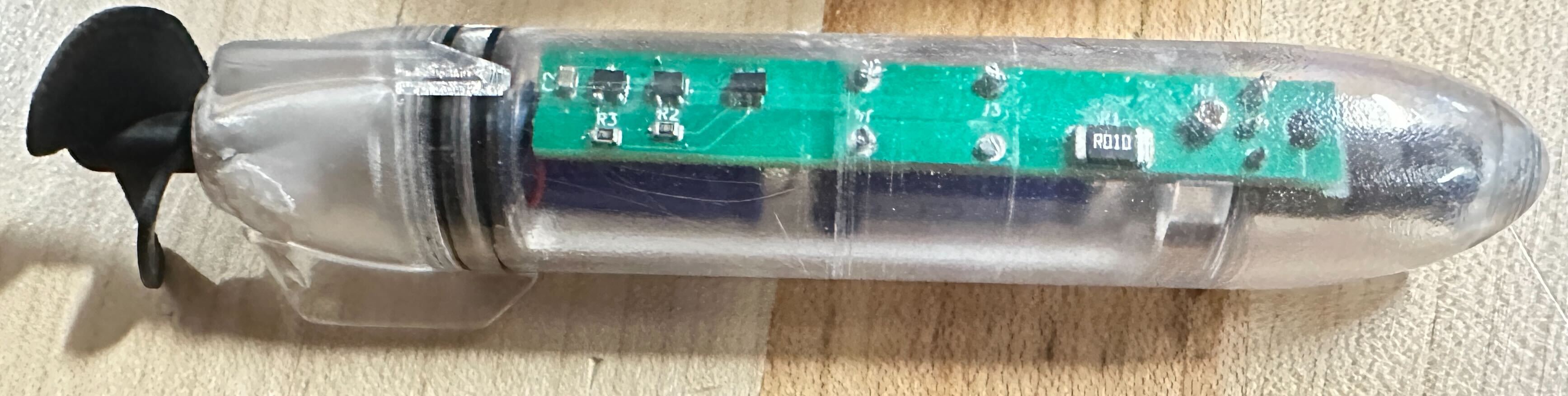
Powered Torpedo V2.
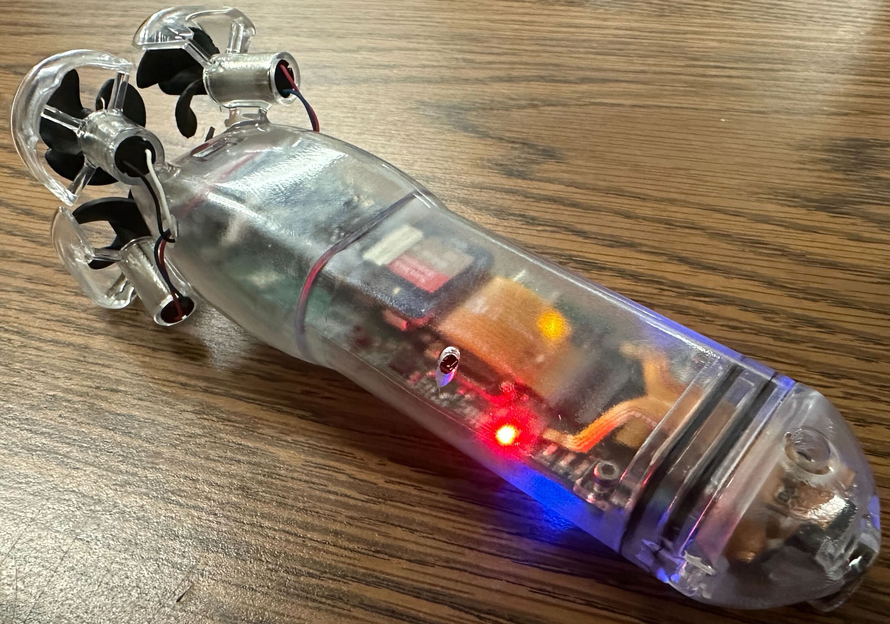
This is the new and improved version of the previous year’s design, focused on improving reliability and usability. Although this second iteration is largely a backup plan for the autonomous torpedo, the mechanical design has been greatly refurbished. In contrast to last year, the powered torpedo is no longer sealed shut, instead using a double o-ring piston seal to keep its electronics dry and accessible in the case of a failure. Additionally, with the charging port now on the inside, there are two fewer hull penetrators to potentially leak water in.
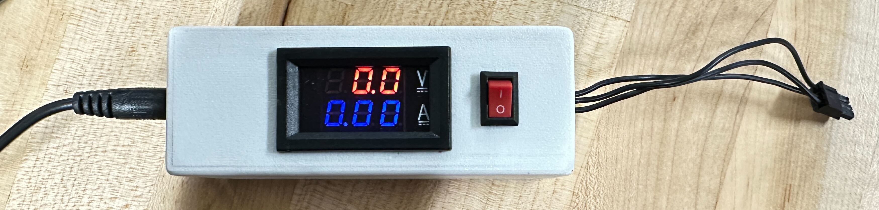
Electrically, it has switched from activating when there is no magnetic field to only activating once the north-pole face of a magnet has moved away. This has greatly improved usability, as a magnet is no longer needed to prevent the torpedo from running when it’s charging. Additionally, the charging circuitry has been moved out to a custom charger, shown here, which shows the voltage and charging current.
Electrical.
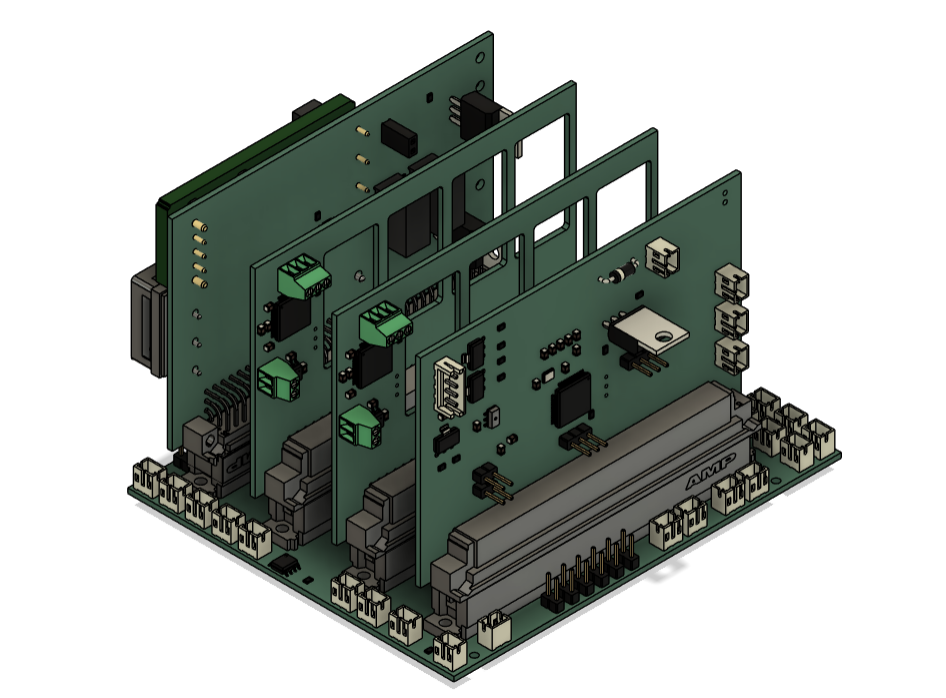
Qubo’s main electrical hull features a backplane system with four daughter card PCBs: a power card, two thruster cards, and a miscellaneous card. Additionally, it uses a separate pneumatics card to actuate solenoid valves controlling Qubo’s end effectors. This year, the power card, backplane, and pneumatics cards were redesigned.
Power Card.
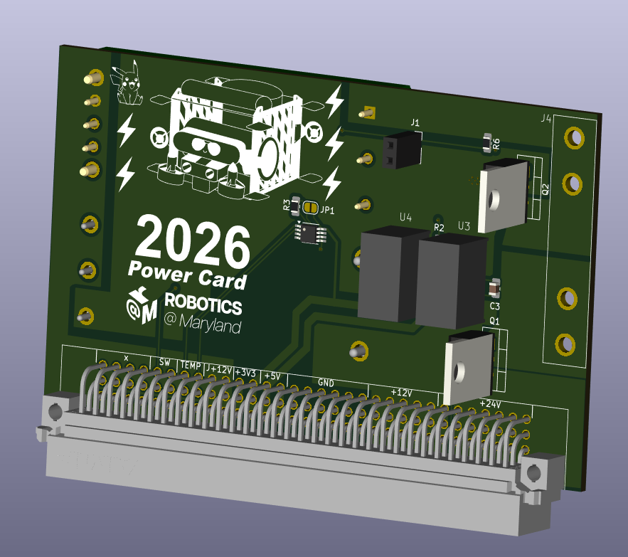
In previous years, there has been a lack of data gathered over the course of testing. For autonomous runs, which are a large portion of test runs, Qubo gets fully turned off before being taken out of the pool. With no way to store or transmit the run data wirelessly, the data is lost when Qubo is turned off. To combat this, a second kill switch was added to Qubo’s power card. This new kill switch cuts off power for everything except for the Jetson. This allows Qubo to be safely taken out of the pool while still retaining its data, which will then be sent over to a connected computer. In addition to this, a temperature sensor was added to the power card in order to ensure that Qubo’s electrical hull is running at safe temperatures.
Backplane.
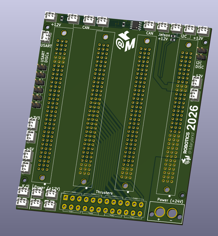
In an effort to make Qubo’s electrical hull easier to work with, the backplane was reorganized to put the pins closer to the wires they connect with. This prevents having to thread wires in between the cards and plugging them in at awkward angles. Connections for the power card’s new kill switch and temperature sensor were also added.
Pneumatics Card.
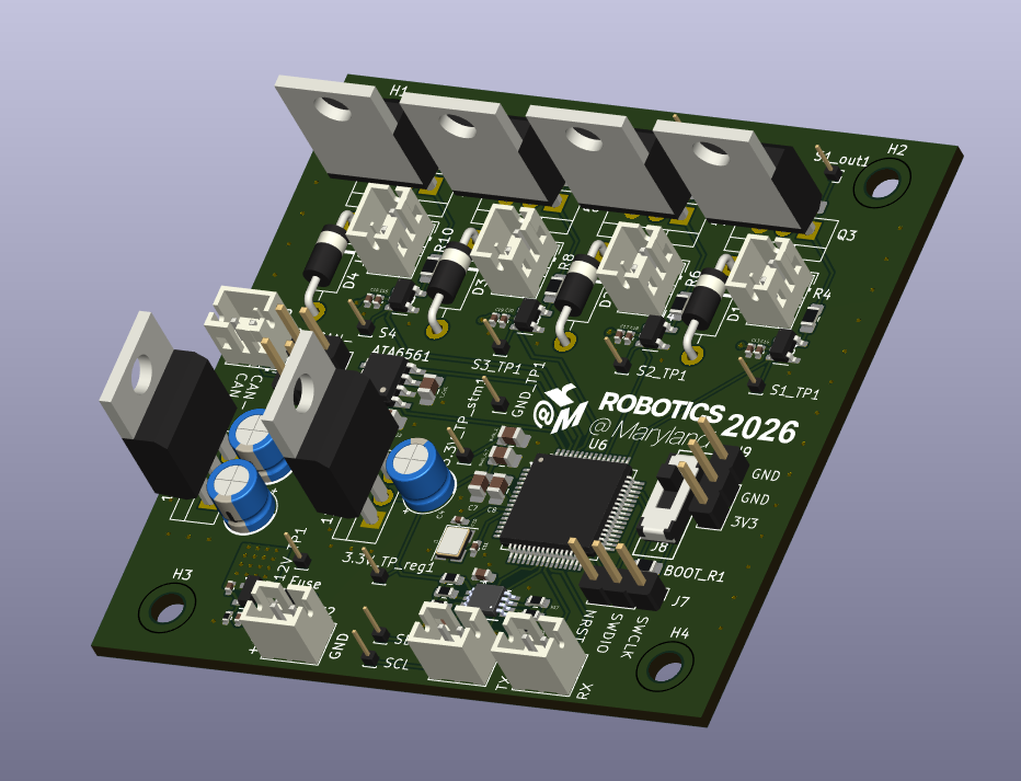
This year, we took the opportunity of redesigning the pneumatics hull to also overhaul the solenoid controller PCB. This board is responsible for triggering the pneumatic actuators onboard the sub. The previous version had three issues: it was vulnerable to electrical spikes, locked into a single communication protocol, and difficult to debug. The new design tackles all three.
Better protection. We added an Adafruit TCA4307 Hot-Swap I2C Buffer to shield the board from I2C bus faults that can occur when components are connected while the system is live. This exact failure mode knocked us out of competition in 2025. We also introduced a custom ramp-rate controller on the 12V line to smooth out the current spikes that occur when the system powers up or a solenoid valve fires.
More flexible communication. The old Adafruit PCA9685 PWM controller was swapped out for an STMicroelectronics STM32G0B1RET6 microcontroller. The STM32 adds some design complexity, but it gives us the ability to support multiple communication protocols. This keeps our current I2C setup working while laying the groundwork for a future transition to CAN bus.
Easier debugging. The new board includes 16 test points (1mm pitch male pinheaders) at key nodes across the circuit, including the I2C bus, CAN bus, power rails, and solenoid excitation rails. That way, any issue can be quickly identified with a lab oscilloscope.
Together, these upgrades make the pneumatics card more robust, flexible, and maintainable heading into competition.
Software.
Computer Vision.
Three exploreHD 3.0 Underwater ROV/AUV cameras (two facing forward, and one facing down) provide us with a comprehensive view of what’s in front of and below Qubo throughout each autonomous run. We apply machine learning and traditional computer vision methods on this data to generate information vital to our overall autonomy systems. We use an object detection model, trained for the RoboSub autonomy challenge, to find the next task to complete and guide Qubo to that task. In past years, we used a YOLOv11 Nano (YOLOv11n) model, but struggled to label thousands of images from scratch for this fully supervised approach. This year, we developed a custom human-in-the-loop automatic labeler. This combines the YOLOv11n architecture with self-supervised, semi-supervised, and hard negative mining components, reducing the labeling overhead to just 100 images per model. We run inference on the LOST labeling platform for rapid labeling of the remainder of the dataset after the first model is trained, and fine-tune the original model for deployment.
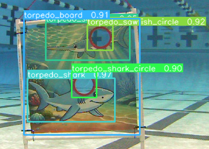
To retrieve the position and orientation of a task, OpenCV’s solvePnP (Perspective-n-Point) method is used. After determining the bounding box from the computer vision model, K-means clustering is applied to group pixels based on color. To reduce background noise, approximately 7% of the pixels are used to form well-defined clusters. This enables the identification of specific feature points on the object that remain consistent across frames. Using these feature points, the image coordinates are mapped to the object’s world coordinates. From this mapping, the translational and rotational vectors for the task are obtained. For example, in the torpedo board task, the features of one of the torpedo circles are isolated. When viewed from a skewed angle, the circle appears as an ellipse, and hence points along the major and minor axes are extracted and passed into solvePnP along with the object’s actual dimensions to accurately estimate position and orientation.
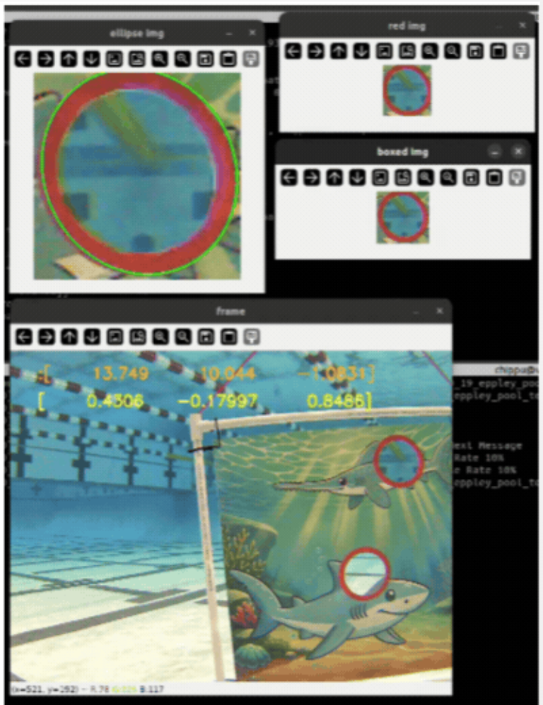
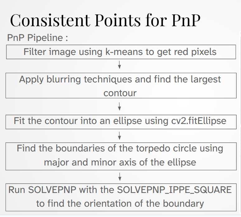
Our autonomy systems use these results to calculate the optimal position to fire a torpedo and visually guide Qubo to that location.
Autonomy.
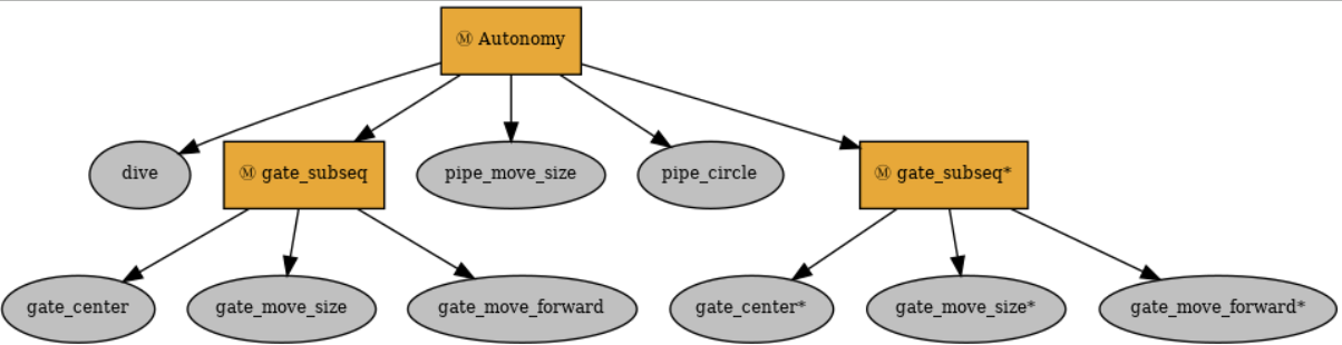
Our autonomy systems are defined in behavior trees, utilizing the py_trees library. Behavior trees provide a way of translating our high-level plans for each task into easily visualizable and understandable graphs that interact with the rest of our software systems. Each behavior we define takes into account information from our navigation and vision systems so that it can make decisions and send commands to our movement control and other end effector systems in order to complete some part of each task. This framework facilitates modular behaviors that can be reused across different tasks and makes it easy to change our high-level strategy for each task on the fly as needed.
Simulation.
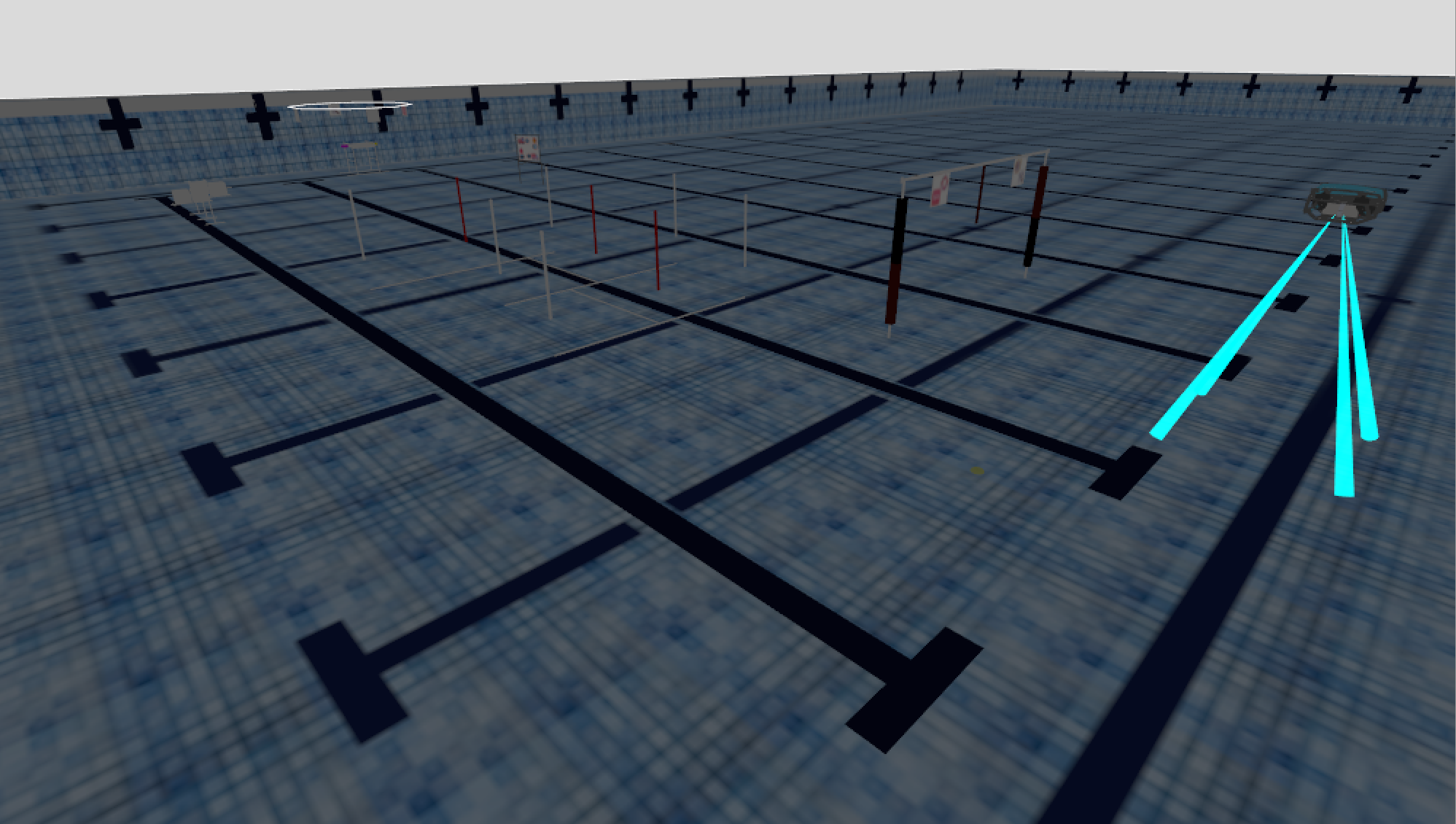
In previous years, our simulation modeled our home pool in the Neutral Buoyancy Research Facility. This simulation did not include any competition tasks, and instead only had the prequalification gate and pipe. This year, we implemented a simulation in Gazebo, modeled and textured with Blender, that is a near exact match of the competition pool at the Woollett Aquatics Center, including all tasks from this year and textures matching the pool markings. We can now use this to test our behavior validity and stability before testing on Qubo in a real pool, making our physical tests more efficient and putting less mechanical fatigue on the robot. This includes testing functionality of our downward-facing camera, more advanced computer vision tasks such as aligning with the torpedo board, and testing full trees from start to finish for a simulated competition run.